Is DNP Protocol Networkable?
How would DNP3 devices work over a complex network?
Let me first explain what I mean. Let us consider a typical Substation Automation. Your substations are generally scattered over a large geographical area. You want to be able to bring back data from your relays, meters and perhaps other devices and to a central location SCADA/HMI to display, record or alarm. Those who are luckier may have fiber laid in the ground to all or some of their substations. In this case, the DNP traffic can ride on the IP backbone to get to the substation device. However, everybody is not that lucky.
I have seen in the past a number of different architectures that engineers use to get to their substation. One common configuration is to have a dedicated link or point-to-point connection from the SCADA master to a master radio. The master station(s) talk to the remote locations (substations). Another possible scenario is that the master needs to talk to a remote node where the node itself has to repeat the message to get it to the final destination. The following figure summarizes the situation:

The following diagram presets the system in a logical diagram:
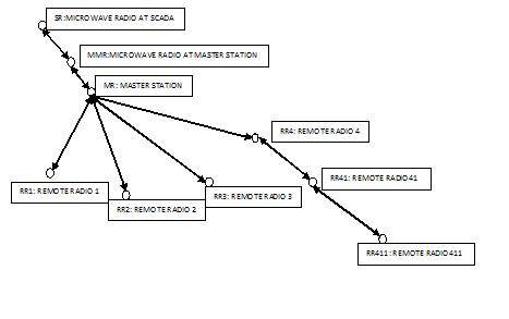
In order to make things easier moving forward, let’s present the following definitions:
Node: A node is a logical point in the network that data can arrive to and/or exit from
Link: Link is a logical space in the network that connects two or more nodes to each other. For example, in the previous diagram, all the circles represent a node and all the arrows represent a link.
Please note that if the master station is set in repeating mode, MR, RR1, RR2, RR3 and RR4 can talk to each other without having to go through a node. So, basically they share the same link. For the sake of this discussion, we assume that the master radio is set in repeating mode.
In the next diagram, I assign some link ID number to the links so that we can easily identify each node:
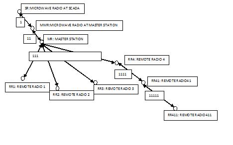
A careful reader may have noticed the following:
· Starting from SCADA master, each node has only one arrival link and multiple exit links. In another work, the topology is more of a directional one that starts from a point (SCADA master) and expands itself to the end devices (substation RTUs). This resembles a typical SCADA system. However, it may pose some limitation on generality, which I will address in a future post.
· The links naming convention follows this rule:
ALn, where AL is the arrival link and n is the order of the exit link. For example, the first link for a node with arrival link 411 is assigned to 4111. Likewise, the 2nd link is assigned to 4112.
Another set of assumptions: let us assume that the each device has a unique DNP address. The following table is just an example of the DNP addresses:
Device | DNP Address |
RR1 | 1 |
RR2 | 2 |
RR3 | 3 |
RR411 | 411 |
SR | 10000 |
This assumption is a realistic one, since for almost all modern RTUs/IEDs you can assign any desired DNP address to the device.
Now here comes the interesting part. The DNP devices are network blind, meaning they do not know where the master or outstation is sitting in the network. However, the nodes are all network aware, meaning they know what the link ID of a DNP device is. For example, link ID for RR1, DNP address 1 is 111, according to the previous document. The nodes can be implemented with a very inexpensive hardware that accepts C or C++ programming. The minimum expectation from a node is to be able to understand the DNP link address in the message and save the link information in the in its permanent memory.
Now, consider an example that the SCADA (SR) wants to send a message to RR2. As mentioned before, SR is network blind. So, the only thing it does is to send the message over the link 1. The message gets to MMR. It has a mapping table that knows the destination DNP address of RR2 (DNP 2) is located at link 111. However, it does not have a link by ID 111. Obviously, it has to send the message over the link 11. MR receives the message on 11. Looking at its own table, MR knows that RR2 is located at 111. 111 is one of the links connected to MR. Therefore, MR simply puts the packet on 111 to get it to RR2. RR2 processes the message and sends the responds to SR (DNP address 1000). RR2 is network blind too. So, the only thing is does is to send the message over the radio on link 111. The message gets to MR. MR realizes that the message is for SR. Using the mapping table, MR finds out the final link destination as 1. 1 is not an immediate link to MR. MR sends the message to MMR. And, through the same process, MMR gets the message to SR.
Like any other architecture, there are some issues with this one two. The firs tissue is that the SCADA or the remote device has to wait for the full propagation delay of the network to receive a massage. If you have a data concentrator somewhere along the line, you are able to cut the time significantly. However, a smart engineer understands that you are not necessarily increasing the speed of receiving information from the field. In addition, I would recommend using this architecture in unsolicited mode. In fact, I always recommend it if possible.
There are several good points about this architecture. You do not need to have full-featured/high-priced DNP concentrators/RTUs at your nodes. You do not need to download a new database into the nodes every time you add/remove a point in the remote DNP devices. Remember, the nodes only look at the DNP link addresses, nothing more. The nodes should only be aware of the network topology, which is something that does not change that often. This architecture works perfectly when you want to address last mile issues or try to access locations with limited RF reach. A node can be added to just extract the signal and carry the message on the rest of the network.
This post was a bit longer than usual and I hope you enjoyed it. Do not forget to email me with your comments.
Take care for now, Rod